Complete refurbishment of the Radiotekhnika U101 amplifier. Complete refurbishment of the amplifier Radiotekhnika U101 Electrical radio circuit diagram for 101 stereo
I would like to tell you about my story of repair and modernization of the Radiotekhnika U-101-stereo amplifier. It seems like a completely ordinary amplifier originally from the USSR, but there is some inexplicable appeal in it ( for me personally), which is difficult to explain.
How can I describe the feeling when you meet a completely unfamiliar girl, your eyes lock with each other, and then her eyes and bodice don’t leave your memory for a long time?... I liked you, she’s beautiful, but your destinies are not destined to be intertwined.
When I first saw/heard Radio Engineering I can’t even remember. But it stuck in my memory, and not just a wild desire to buy and listen, no, just a pleasant image. And then the other day the thought materialized and fate gave me RT 101 as a gift. Tired, tormented by everyday life and lack of attention.
I wish my wife didn’t read these lines, otherwise she’ll get jealous and call her crazy
:love: To put up with malfunctions and terrible things technical condition I can’t, I have no peace. Therefore, instead of flowers and sweets for my wife, I regularly buy capacitors, microcircuits, resistors, etc....
I decided to bring RT back to life. To begin with, the following had to be overcome:
1. Transformer hum.
2. The same terrible hum in the speakers.
3. Clap when turned on and some kind of scary sound when turned off.
4. Signal indicator not working.
5. Noisy regulators.
The first step was to replace all electrolytic capacitors. Everything is according to the original ratings, the only thing in the power supply is that the capacity has been slightly increased: 2x2200+ 2x4700 uF to power the final stage (C3, C4, C8, C9 in the diagram). KD209A diodes are replaced with “ultrafast” UF4007.

I will say right away that this operation almost eliminated the first three points of problems.

It was not possible to revive the indicator by simply changing the capacitors, but that’s what I wanted little blood... He continued to show the entire scale without reacting to anything. While clarifying the reasons on the forum, we came to the conclusion ( possibly false) that the K161PP2 microcircuit has failed. Finding one, you understand, is not easy. Easier than a complete indicator.
The world is not without good people (believe in it, do good yourself and the result will not take long) and the indicator, together with the ULF-P of the latest revision, the one on the same chip, was given to me by the broadest-hearted man Vasily (Skif on Vegalab). For which I bow to him and be very grateful!!! True, the functionality of the modules was in question.
In the purchased indicator, we had to replace the trimming resistors, which were covered in nail polish and became unusable. The indication of one channel is working!!! But we have a stereo... I didn’t suffer for a long time, but immediately decided to replace the K157UD2. The operation was a success and that unforgettable green spark appeared in RT’s eyes again.

Further more.
The sound after restoration was mesmerizing with bass. It would seem that 2x 20 W, and such bass that the windows tremble, the plasterboard partition in the kitchen vibrates, and in the evening, while watching a movie at a volume level below average, the neighbor from downstairs called and asked in a sweet, restrained voice to turn down the volume.
But the happiness did not last long. After reading strangers opinions and reviews about how much better the single-chip pre sounds, less distortion, etc., I decided to change my native one. ( For the sake of the authenticity of the article, I will inform you that it was replaced at the stage of work with the indicator. Before this, the ULF-P of the old revision was listened to for a couple of weeks.) And at first I really heard ( or wanted to hear) all these advantages: “high-end detail”, “clearer scene”, “grainy mids”, etc.
But in the depths of the soul there is no peace, there is no pleasure when listening, only self-deception driven into the head by meaningless terms. This was no longer the girl I knew.
A week of listening was enough to understand that it was necessary to return the original ULF-P on three microcircuits. But here’s the problem, I had already started to burn bridges when I removed one K157UD2 (DA 1.* in the diagram) from the dismantled preamplifier, which was used to repair the indicator. I was puzzled by the search for information, understood in more detail the structure and operation of 101. I came to the conclusion that exclusion from the DA 1.* scheme does not lead to negative consequences. (DA 1.* in the preamplifier serves to match the piezoceramic pickup, for me this is not relevant).

The signal from the source after the input selector is supplied to R9 and R10, respectively. Interstage capacitors C23, C24 were replaced out of harm's way with new non-polar ones. First launch after modernization: a lot of worries and one small hope to return the former voice...
From the first notes of familiar compositions, I realized that the goal had been achieved, the bass lived in 101 again! I don’t know how to describe the sound in a sweeping manner, I’ll simply say: you either like it or you don’t. Now I like it! Thus, as a result of related events, the third version of the pre-amplifier RT 101, two-chip, appeared.
The popping sound in the speakers when turned on was the result of a malfunctioning protection. Extraneous sounds when the amplifier is turned off, just like the reaction to turning on/off household appliances in the apartment, it was eliminated by installing a noise-suppressing capacitor with a capacity of 1 μF and a voltage of >280V on the contacts of the power switch.
The volume, balance and tone controls are cleaned of dust by air flow and lubricated (Ciatim 201 lubricant).
In addition to the preamplifier, the following changes were made to the RT 101 design:
The original input switch along with the corrector amplifier has been removed.

Instead of the original one, the input selector for three sources is made on a biscuit, which previously served as a “Copier” switch in the amplifier (SA2 on). The switch has 4 pairs of contacts, so it allows you to break even the ground of incoming signals.
The connectors for connecting sources are standard RCA, two pairs on the rear wall and one for “hot plugging” sources on the front panel (in the places where the “five” connections of tape recorders were previously located). After removing unused switches and connectors, the holes on the front panel are closed with aluminum-look plugs (Dubond material).

IN result The amplifier has lost its value for museums, but is compatible with modern sources and works.
This completes the first part of the work. The second is more complex, since it was decided to refine the body and give it a final “gloss”. I plan to veneer the top cover, make a new bottom, and properly design the back panel with connectors. Which I will definitely tell dear readers about in the second part of the article.
The Radiotekhnika U-101-stereo amplifier is designed for high-quality amplification of audio frequency signals both from devices included in the complex and from external sources of sound programs. The amplifier has an electronic input switch, electronic output power level indicators separated by channels, and a device for protecting the output stages when short circuit under load; protection of the loudspeakers is also provided against the possible contact of a constant voltage component in the event of amplifier malfunctions, as well as protection of the output stage transistors from overheating.
Main technical characteristics of the Radiotekhnika U-101-stereo amplifier
- Rated output power, W: 2x20
- Nominal range of reproduced frequencies, Hz: 20...20 000
- Nominal input voltage, mV, input:
pickups: 2
others: 200 - Harmonic coefficient in the nominal frequency range, %, no more: 0.3
- Signal/background ratio, dB: 60
- Signal-to-noise ratio (weighted), dB, at 50 mW output power: 83
- Output voltage for connecting headphones (R H =16 Ohm), V: 0,9
- Power consumption, W: 80
- Dimensions, mm: 430X330X80
- Weight, kg: 10
Diagram of electronic switches for amplifier inputs Radiotekhnika U-101

Fig.2.
The electronic switches of the amplifier inputs are made on DA1-DA3 microcircuits (Fig. 2), controlled by a constant voltage coming from the input selector - roll switch SA1. This circuit design simplified installation, eliminated noise when switching inputs, and reduced interference on the input circuits. The microcircuits are located directly next to the input connectors, and the switch is on the front panel of the amplifier.
Switch SA2 “Copier” is also connected to the switching board. It is designed for quick switching of tape recorders (without additional manipulations with connecting cables) when dubbing phonograms. The switching is purely mechanical, which allows, in the absence of the need for control listening, to carry out this work without connecting the amplifier to the network.
Circuit diagram of final amplifiers "Radio Engineering U-101-stereo"

Fig.3.
Unified ULF-50-8 modules were used as the final amplifiers of Radiotekhniki U-101-stereo. The input stage of the module (Fig. 3) is differential on transistors VT2, VT4 with a current source (VT1, VT3) in the emitter circuit. The next stage on transistors VT5-VT10 is also differential, with a dynamic load in the form of a current mirror (VT5, VT8), providing symmetrical drive of the output stage. High linearity of amplification of large signals by this part of the module is ensured by an increased (compared to the output stage) supply voltage.
The output stage (VT13-VT20) is symmetrical, based on composite emitter followers with parallel connection transistors in the last stage. Temperature stabilization of the cascade operating mode is provided by a device based on the VT9 transistor.
Amplifier protection circuit Radiotekhnika U-101

Fig.4.
The amplifier overload protection device is assembled using transistors VT11, VT12 and diodes VD3-VD6. When the load is short-circuited, it limits the output current to 2 A. As already mentioned, “Radio Engineering U 101 Stereo” also provides protection for loudspeakers from contact with DC voltage in the event of an amplifier malfunction and protection of the output stage transistors from overheating. The AF voltage is supplied to the loudspeakers through the contacts of relay K1 (Fig. 4). If the amplifier is working properly, it operates 3...5 s after turning on the power, which eliminates clicks caused by transient processes in the amplifier. The delay time for connecting the speakers is determined by the parameters of the R10C3 circuit. With the appearance of a constant component (more than 2 V of any polarity), transistors VT1, VT2 generate a voltage that goes to the base of transistor VT3 and closes it. As a result, the winding of relay K1 is de-energized, and its contacts disconnect the speakers from the amplifier.
The same device is used to automatically turn off the speakers when the headphone plug is inserted into the XS17 connector, equipped with an SA3 switch, and the powerful transistors overheat.
The thermal relay is assembled on the DA1 chip. The functions of the thermistor are performed by the VT transistor, connected to one of the arms of the bridge R12R13R16R17. The bridge is powered by a stabilized voltage through resistors R14, R15. In the initial state, with an appropriate choice of high-precision resistors, the bridge is unbalanced in such a way that the voltage at pin 5 (relative to pin 4) of the DA1 microcircuit is 50 ± 5 mV, and there is no voltage at its pin 10. When the VT transistor (it is located on the heat sink of the output stage transistors) is heated to 86...90°, the bridge is balanced, and the voltage at the output of the microcircuit jumps up to the supply voltage (+26V). As a result, it opens transistor switch VT4, and the protection system disconnects the loudspeakers from the final amplifiers.
Circuit diagram of an electronic indicator of the output power level of the amplifier Radiotekhnika U-101

Fig.5.
A schematic diagram of an electronic output power level indicator with information output to a vacuum cathodoluminescent two-color display is shown in Fig. 5. When the output power is less than the rated one (-20...0 dB), the green bar lights up, and when there is an overload (0...+5) dB, the red bar lights up. The operation of the HL1 display is controlled by the DDK chip, which provides analog-positional conversion of the output signal of each amplifier channel into the appropriate code. The threshold voltages for operation of the switching elements of the microcircuit are stabilized by a current generator on transistor VT2. The inverter on the transistor VT1, together with the elements of the DDI microcircuit, forms a generator of paraphase pulses arriving at the display grids in time with the connection of the inputs of this microcircuit to the outputs of the op-amp DA1.1, DA1.2. The pulse frequency is chosen to be 150 Hz, it is determined by the ratings of the elements R11, C6. Processing information from both channels with one analog-position converter ensures perfect consistency of display characteristics. Microcircuit DA1 amplifies signals coming from rectifiers on diodes VD1, VD2 through integrating circuits R1C1R4, R2C2R5 (indicator integration time is about 30, reverse time is 500 ms). Parametric stabilizers (VD4, VD5) provide stable indicator readings with significant changes in supply voltages.
A product of the Latvian industry, Radiotehnika U-101-stereo (later, Radiotehnika U-7101) was a desirable acquisition for any music lover in the mid-eighties. The complete set of Radiotehnika equipment consisted of at least four units - an amplifier, a tuner, a cassette deck, and a vinyl player. There might be something else, but I didn’t come across it.
Some time ago, I found myself alone with a Radiotehnika U-101-stereo amplifier, a Radiotehnika M-201-stereo cassette deck and a pair of Romantika 25AC speakers. There was a lot of time, there was nothing to do, next to the dream of a music lover of the mid-eighties there were cassettes with recordings of The Beatles and Al Bano & Romina Power. It was decided to listen to Felicita and Let it be, but that was not the case. The cassette deck didn't spin cassettes, and the amplifier produced such background noise that it was scary for the speakers.
With the cassette deck, everything was resolved quite simply - a little liquid lubricant, a bottle of cologne and a splash of vodka brought the old lady to her senses. Here is a small photo report:
Just pour alcohol and oil on top of everything, and glue the cracked plywood body together. This, of course, will not last long, because... and the gears were brought up and the belts stretched
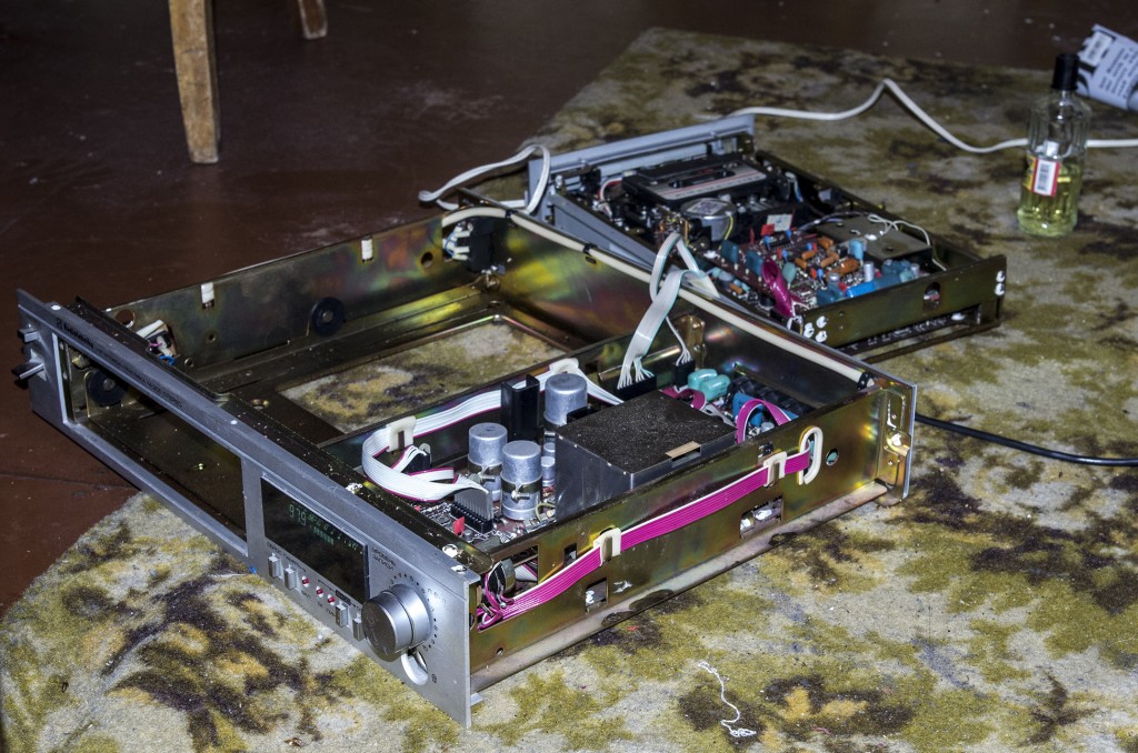
With the amplifier, in principle, everything is also quite simple. All the salt is in the electrolytes :) As it turned out after five minutes of studying the problem via Google, it is enough to replace a couple of electrolytes in the HF unit and it is possible to replace the electrolytes at a high level. Here is a small photo report:


Since I didn’t remember which pair of electrolytes to change in the RF unit (such a small shielded box with a cold contact plugged into the main board), I had to replace everything. Likewise with high electrolytes. Everything was aggravated by the fact that I didn’t have a multimeter, and I didn’t have a soldering iron either. I had to buy everything in the same place where I came for electrolytes. DIN 5 pin and TRS 3.5mm connectors were also purchased just in case.
As a result, everything took about 40 minutes of work and the dream of a music lover of the mid-eighties began to sing first in the voice of Al Bano, and then with the Moby synthesizer, taking the signal from a mobile phone.


It is soldered, disassembled and assembled quite easily, I soldered with a decent Chinese 100W soldering iron. All parts are available and distributed, for high - six pieces 50V 2000uF, for low - a pair of 6.3V 50uF, a pair of 10V 20uF and a pair of 50V 2uF. You just need to keep in mind that the tracks from the RF block board peel off easily and naturally, and you need to solder carefully so as not to tear anything. Otherwise, you will have to “duplicate” the tracks with electrolyte legs.
Yes, I almost forgot, the amplifier circuit:
- (PDF, 100KB)
- (PDF, 100KB)
It seems that the time of the Land of Soviets has long passed, but many enthusiasts still use Soviet technology and sincerely believe that there is nothing better than it in the world. This especially applies to all kinds of amplifiers, speakers and players. They say that only they provide the most “correct”, clear and warm (tube) sound. Let's not argue with this. Moreover, Soviet audio technology was really at its best. One of the “oldies” that can still please you with high-quality sound is the Radiotekhnika U-101 amplifier. An important role is also played by the fact that it was assembled not in the Russian expanses, but in the union Latvia. Therefore the quality is appropriate. However, it’s time to look at the main characteristics of this device and consider the reviews of the happy owners of this “miracle”. But first a little general information about the manufacturer.
About the manufacturer
Once upon a time, the Radiotekhnika company was a subsidiary of the well-known VEF plant. The latter was abolished in 1997. But Radiotekhnika remained and is still operating today. now this largest producer musical equipment in Eastern Europe. The history of the company began in 1927. Then Abram Leibovitz founded a small enterprise producing radios. Over time, the company grew and began to produce a huge amount of consumer electronics: from radios and televisions to amplifiers and acoustic systems. Legendary S90 speakers were designed and released in 1989. The development of such a thing as the Radiotekhnika U-101 amplifier dates back to approximately the same time period.
It’s worth noting right away that sophisticated “audiophiles” do not value the equipment of this manufacturer. They consider it mass "slag" and "trash". The only thing these comrades from Soviet audio systems recognize are the top amplifiers from Amphiton and the legendary Brig. But in any case, the Radiotekhnika U-101 amplifier is stereo ten times better than that Chinese junk that is now on the shelves of electronics stores. Therefore, for scoring small rooms (such as a standard apartment), it can and should be purchased. Moreover, on secondary market this device costs pennies. However, let's move on to the design features of the amplifier and its technical specifications. For this the most important.

Appearance and Design
So, let's look at the Radiotekhnika U-101 stereo amplifier. Its design is, in principle, standard for devices from this manufacturer of the 80s of the last century. However, the massive front panel made of brushed aluminum inspires a certain confidence. The clean wood that decorates the rest of the body also evokes some positive emotions. But most of all I was pleased with the buttons for switching operating modes and the volume, balance, bass and treble controls. They are made well (from the same aluminum), and the size is such that you definitely won’t miss them. All these are distinctive features of Soviet audio equipment of those times. And “Radio Engineering” also looks the part. However, the designers did not forget about cooling the internal elements of the device. High-quality metal grilles are located both in the upper part of the body and in the lower part. The rear panel has a massive power supply refrigerator and a large number of necessary connectors (mostly five-pin). The back panel is also made of metal.

Weight and dimensions
Soviet technology was not compact. The Radiotekhnika stereo amplifier is no exception. Its dimensions are quite impressive. Its width is 330 mm. Length - 430 mm. And the height is 80 mm. Quite a voluminous device. To install it you will have to find a suitable place. The ideal option would be a rack for equipment. They were produced (and were very popular) in the 90s of the last century. But even now there is such furniture. It’s just that now the dimensions of such shelves are tailored to Chinese “receivers”. But this amplifier has to fit there. As for weight, this amplifier weighs an impressive 10 kg. This weight is due to the heaviness of the power supply, individual components and metal design elements. But it is immediately clear that we have a solid, high-quality Soviet system. Now let's move on to the technical characteristics of the amplifier. They determine the quality of the reproduced sound.

Amplifier Specifications
So, let's move on to the technical characteristics of the amplifier. It is worth noting that it is not suitable for lovers of loud music. Its rated output power is only 20 watts per channel. For scoring a standard room it is quite enough. But nothing more. The resistance is 4 ohms for each channel. This means that huge 8-ohm floor-standing speakers (like Amphiton) cannot be connected to it. He simply won't be able to swing them. Most the best option- bookshelf speakers. They are the ones most suitable for such a thing as the Radiotekhnika amplifier. The characteristics are quite modest. Even by Soviet standards. But it ensures high sound quality. The range of frequencies reproduced by the amplifier ranges from 20 to 20,000 Hertz. This is quite enough to provide high-quality sound. If you connect this amplifier to a computer, you must use an external DAC. Only he can unleash the full potential of this amplifier.

Dealing with extraneous noise
Active noise cancellation is a very good thing in any amplifier. Unfortunately, the Radiotekhnika amplifier is deprived of this useful option. There are noises. But they are not so noticeable to the naked ear. The signal to weighted noise ratio is 83 decibels. And the signal-to-background ratio is 60 decibels. It's pretty good characteristics. Harmonic distortion at low frequencies is no more than 0.2%. For the untrained reader, these numbers mean nothing. But they can be explained more simply. This amplifier is capable of providing high-quality sound of any composition, even at its maximum volume, with minimal distortion. And this is the most important thing in any amplifier. If only for this reason, Radiotekhnika U-101 is much better than the Chinese consumer goods that are now flooding store shelves. Therefore, if you have the opportunity to purchase “Radio Engineering,” you should not lose the chance to become the owner of high-quality equipment.

Amplifier circuit and its maintainability
The “Radio Engineering” amplifier circuit makes it clear that this is a high-quality device from Soviet Union. Nobody does it that well anymore. In the Union, equipment was created to last for decades. Now all companies are chasing profit. Therefore, modern technology works until the first breakdown. Then you need to go buy a new device. Here all the parts are interchangeable. Even if some components have already been discontinued, you can find an analogue, install it, and the amplifier will work again for another ten years. According to statistics, the first thing that fails in Radiotekhnika amplifiers is capacitors. Fortunately, there is enough such goodness on the radio markets. Overload protection also fails quite often. This is more complicated, since some of its components are no longer produced. But there are no problems with replacement, since modern ones with the same capacity are suitable.

What other “sores” does the “Radiotekhnika U-101” stereo amplifier have? The diagram clearly shows that the lion's share of space in the device case (and on the printed circuit board) is occupied by the power supply and its components. If it burns then it will begin headache. They don’t make them like this anymore, and finding modern analogues is not so easy. But there is one plus: the power supply is the least likely to fail. Only a few such cases are known. The fact is that this block is equipped with excellent stabilizers. Therefore, its failure occurs very rarely. And in most cases, it will be enough to replace a resistor with identical markings. This amplifier is completely repairable. And this is another advantage. Almost anyone with a soldering iron can fix it. You just need to understand at least something about radio electronics.
Comparison with other amplifiers
This is a very important step. You need to take into account all the nuances and understand whether the Radiotekhnika amplifier is better or worse than the rest. The first competitor is Amphiton-001. Under the same playing conditions, our hero showed a much more complete sound scene than Amphiton. Further more. The bass of "Amfiton" could not become as correct and fast as the bass created by "Radiotekhnika". A clear failure. The next test subject was the legendary "Brig U-001". This monster of sound easily made a simple 101. The Brig produced a much better sound. And nothing could be done about it. Although "Brig" is years older, it is much better than "Radio Engineering". The only trouble is that it is very difficult to find an adequate “Brig” on the secondary market. Therefore, "Radio Engineering" remains the best option. And an inexperienced listener will not notice much difference between these two amplifiers.
Positive reviews about "Radiotechnics"
What those who have already purchased say preamplifier"Radio engineering U-101"? The vast majority of owners are satisfied with the sound this amplifier provides. Others note that after a little modification the device began to sound even better. But all music lovers agree on one thing: this amplifier is easy to use. It is perfect for everyday use. Another advantage people consider is the ease of repairing the amplifier if it fails. In general, the owners are satisfied with the device.
Negative reviews about "Radiotechnics"
The Radiotekhnika amplifier received negative reviews only from those who consider themselves “audiophiles.” The most common complaint from these comrades is insufficient scene depth. They also complain about the development of low and high frequencies. But this is not a top-end amplifier. If you want this kind of sound, you need to purchase a device for several thousand dollars. And "Radio Engineering" is an entry-level amplifier. So such complaints should not be taken into account.
Conclusion
So, we looked at the Radiotekhnika U-101 pre-amplifier. This is a high-quality and reliable device that can provide high-quality sound at minimal cost. You can buy this amplifier on the secondary market for pennies. And in good condition. Another reason to provide yourself with high-quality equipment. Even though it comes from the past.
 Cheesecakes from cottage cheese in a frying pan - classic recipes for fluffy cheesecakes Cheesecakes from cottage cheese for 500 grams recipe
 The easiest zucchini casserole in the oven
 Cabbage with grapes: preparing unusual dishes Marinated cabbage with grapes and cranberries