Designation on the diagrams of radio components. Drivers L293D, L298, TB6612 – H-bridge motor control H bridge on bipolar transistors
Distinctive features:
- Overheat shutdown
- Overcurrent shutdown
- Starting current limited by soft start function
- ESD protection
- Status feedback
- Sleep mode for direct battery connection
- Work with and without braking
- A brief description of:
- On-channel resistance Rds(on) 12 mOhm
- Operating supply voltage V cc.op. 5.5…35V
- Continuous load current I cont. (Ta = 85°C) 7.0A
- Current protection threshold Ishutdown 30A
- Operating frequency 20 kHz
Typical connection diagram:
Block diagram:

Pin locations:

Description of pins:
Description:
IR3220 is a high level dual switch integrated circuit. Together with two lower-level switches, for example, IRF741), IR3220 organizes a controlled H-bridge. It provides per-arm loss of control protection, H-bridge control logic, soft start, and overcurrent and overvoltage protection. Signals IN1 and IN2 set the operating modes and activate a sequence of PWM cycles for a smooth start to limit the inrush current. When using the specified type of transistor and proper cooling, the internal system of the chip that controls the high-level switches protects the operation of the entire -H-bridge. The soft start duration is set by the external RC circuit time constant and resets automatically.
Documentation:
In various electronic circuits, it is often necessary to change the polarity of the voltage applied to the load during operation. The circuitry of such devices is implemented using key elements. The keys can be made on switches, electromagnetic relays or semiconductor devices. The H-bridge on transistors allows, using control signals, to switch the polarity of the voltage supplied to the actuator.
Used in various electronic toys, some household appliances, and robotics. commutator motors DC, as well as bipolar stepper motors. Often, to perform an algorithm, it is necessary to quickly change the polarity of the supply voltage using an electrical signal so that the motor technical device began to rotate in the opposite direction. So the robot vacuum cleaner, having bumped into a wall, instantly turns on the reverse and in reverse moves away from the obstacle. This mode is implemented using an H-bridge. The H-bridge circuit also allows you to change the rotation speed of the electric motor. To do this, pulses from a pulse-width modulator (PWM) are supplied to one of the two switches.
The engine mode control circuit is an h-bridge. This is a simple electronic circuit that can be made using the following elements:
- Bipolar transistors
- Field effect transistors
- Integrated circuits
The main element of the circuit is an electronic key. Schematic diagram The bridge resembles the Latin letter “H”, hence the name of the device. The circuit includes 4 keys arranged in pairs, left and right, and a load is connected between them.

The diagram shows that the switches should be turned on in pairs and diagonally. When keys 1 and 4 are turned on, the electric motor rotates clockwise. Keys 2 and 3 ensure that the engine operates in the opposite direction. When you turn on two keys vertically on the left or right, it will happen short circuit. Each pair horizontally short-circuits the motor windings and rotation will not occur. The following figure illustrates what happens when we change the position of the switches:

If we replace the switches in the circuit with transistors, we get this (extremely simplified) version:

In order to eliminate a possible short circuit, the h-bridge on transistors is supplemented with input logic, which eliminates the occurrence of a short circuit. In modern electronic devices bridge circuits for changing polarity are complemented by devices that provide smooth and slow braking before turning on the reverse mode.
H-bridge on bipolar transistors
Transistors in key circuits operate on the principle of valves in the “open-closed” mode, so large power is not dissipated on the collectors, and the type of transistors used is determined mainly by the supply voltage. A simple h-bridge using bipolar transistors can be assembled independently using silicon semiconductor devices of different conductivities.
 H-bridge on bipolar transistors
 This device allows you to control a low-power DC motor. If you use transistors KT816 and KT817 with index A, then the supply voltage should not exceed 25 V. Similar transistors with indexes B or D allow operation with voltages up to 45 V and a current not exceeding 3 A. For correct operation of the circuit, transistors must be installed on radiators . Diodes protect powerful transistors from reverse current. As protective diodes, you can use KD105 or any others designed for the appropriate current.
The disadvantage of this scheme is that high potential cannot be applied to both inputs, since opening both switches at the same time will cause a short circuit in the power supply. To eliminate this, integrated bridge circuits provide input logic that completely eliminates the incorrect combination of input signals.

The bridge circuit can be changed by placing more powerful transistors in it.
N-bridge on field-effect transistors
In addition to using bipolar transistors in bridge power management circuits, field-effect transistors (MOSFETs) can be used. When choosing semiconductor elements, voltage, load current and switching frequency of switches are usually taken into account when using pulse width modulation. When a field-effect transistor operates in switching mode, it has only two states - open and closed. When the key is open, the channel resistance is negligible and corresponds to a resistor of a very small value. When selecting field effect transistors For key circuits you should pay attention to this parameter. The higher this value, the more energy is lost in the transistor. With minimal channel resistance, the efficiency of the bridge is higher and its temperature characteristics are better.
An additional negative factor is the dependence of the channel resistance on temperature. With increasing temperature, this parameter increases noticeably, therefore, when using powerful field-effect transistors, appropriate radiators or active cooling circuits should be provided. Since the selection of field-effect transistors for a bridge is associated with certain difficulties, it is much better to use integrated assemblies. Each contains a complementary pair of two power MOSFET transistors, one with a P channel and the other with an N channel. There are also damper diodes installed inside the case to protect the transistors.

The following elements are used in the design:
- VT 1.2 – IRF7307
- DD 1 – CD4093
- R 1=R 2= 100 kom
Integrated circuits with H-bridge
In H-bridge switches, it is desirable to use complementary pairs of transistors of different conductivities, but with the same characteristics. This condition is fully met by integrated circuits that include one, two or more h-bridges. Such devices are widely used in electronic toys and robotics. One of the simplest and most affordable microcircuits is L293D. It contains two h-bridges that allow you to control two electric motors and can be controlled by a PWM controller. The microcircuit has the following characteristics:
- Power – +5V
- Electric motor supply voltage – + 4.5-36 V
- Output rated current – 500 mA
- Pulse current – 1.2 A
The L298 chip also contains two h-bridges, but with much greater power. The maximum supply voltage supplied to the motor can reach + 46 V, and the maximum current corresponds to 4.0 A. The TB6612FNG H-bridge allows the connection of two commutator motors or one stepper. The switches are made on MOSFET transistors and have protection against overtemperature, overvoltage and short circuit. The rated operating current is 1.2 A, and the maximum peak current is 3.2 A. The maximum pulse width modulation frequency should not exceed 100 kHz.
Bridged motor control devices are often called drivers. Drivers are also called microcircuits that only provide control of powerful key cascades. Thus, the HIP4082 driver is used in the control circuit for a powerful electric motor. It provides management of keys assembled on discrete elements. They use IRF1405 MOSFET transistors with N-channels. Texas Instruments produces a large number of integrated drivers designed to control electric motors of various designs. These include:
- Drivers for stepper motors – DRV8832, DRV8812, DRV8711
- Drivers for commutator motors – DRV8816, DRV8848, DRV8412/32
- Drivers for brushless motors – DRV10963, DRV11873, DRV8332
Available on the market big choice integrated bridge circuits for controlling any electric motors. You can make the design yourself by using high-quality discrete elements.
To control motors, so-called H-bridges are used, which make it possible to cause rotation in both directions by supplying control logic signals to the inputs. In this article I have collected several options for H-bridges. Each has its own advantages and disadvantages, the choice is yours.
OPTION #1This is a transistor H-bridge, its dignity is its ease of manufacture, almost everyone has parts for it in the trash, and it is also quite powerful, especially if you use KT816 and KT817 transistors instead of KT814, KT815 indicated in the diagram. Log.1 cannot be supplied to both inputs of this bridge, because a short circuit will occur.
OPTION #2
This H-bridge is assembled on a microcircuit, its advantage is that it is one microcircuit :-), and also the fact that it already has 2 H-bridges. The disadvantages include the fact that the microcircuit is low-power - max. output current 600 mA. A PWM signal can be supplied on line E to control the speed; if this is not required, then pin E must be connected to the power positive.
OPTION #3
This control option is also on a chip, more powerful than the L293D, but it has only one bridge. The microcircuit comes in three versions S, P, F. The figure shows option S. Option P is more powerful, and option F is for surface mounting. All microcircuits have different pinouts; for others, see the datasheet. By the way, this circuit allows you to apply units to both inputs, this causes engine braking.
OPTION #4
This bridge is assembled using MOSFET transistors, it is very simple and quite powerful. Two units cannot be fed to it at the same time.
There are still quite a lot of motor control chips (for example TLE4205, L298D), but the ones mentioned above are the most popular. You can also assemble an H-bridge using conventional electromagnetic relays.
Let's look at an electric motor driver based on transistors and the L298 microcircuit, and understand the operating principle of the H-bridge. Let's find out the features of connecting drivers on L298 to different engines and power supplies, we will conduct simple experiments with stepper motors and motors DC voltage. Connection to Raspberry Pi and simple programs for driver control test.
What is an H-bridge
When designing machine tools, robots and other automated devices, it becomes necessary to control a DC motor or stepper motor coils. In order to be able to control the motor winding and make its shaft rotate in different sides, it is necessary to perform switching with polarity reversal. For this purpose, the so-called “H-bridge” is used.
Why this name? - because the circuit for switching on the motor and switches for switching resembles the Latin letter H. The operating principles of the H-bridge are shown in the figure below.
Rice. 1. How the H-bridge works, the principle of switching the motor for rotation in different directions.
As you can see, with the help of 4 switches we can connect the motor to the power source in different polarities, which in turn will make its shaft rotate in different directions. The switches can be replaced with relays, or with powerful electronic switches with transistors.
It is important to note that it is NOT possible to allow two switches to be shorted on one side of the H-bridge, as this will result in a short circuit. When designing a bridge circuit, you need to incorporate this rule into the logic and thus implement protection.
Circuit of a simple H-bridge using silicon transistors
You can assemble a simple DC motor driver (or for the winding of a stepper motor) using common silicon transistors.
![]()
Rice. 2. Schematic diagram of a simple electric motor driver using silicon transistors.
Such a driver allows you to control a DC electric motor with a supply voltage of up to 25V (for KT817A, KT816A) and up to 45V (for KT817B-G, KT816B-G) with a current of no more than 3A. With a large operating and load current of the motor, the output transistors KT817 and KT816 must be installed on radiators of sufficient size.
The installation of diodes VD1-VD2 is required; they are needed to protect the output transistors from reverse current. In their place, you can put domestic KD105A or others with a higher current.
By assembling two such circuits (2x6 transistors), you can also control a stepper motor or two DC motors.
In order not to fence a garden of 12 transistors, you can use specialized microcircuits; below we will look at an example with the L298 microcircuit and a ready-made unit based on it.
L298 chip, characteristics and capabilities
The L298 IC is a powerful universal bridge driver for controlling DC motors, stepper motors, electromagnetic relays and electromagnets (solenoids). The chip contains two H-bridges, made on powerful transistors, as well as TTL compatible logic.

Rice. 3. L298 chip in Multiwatt15 PowerSO20 packages.
Main technical characteristics:
- Operating voltage - up to 46V;
- Maximum direct current - 4A (with radiator);
- Low saturation voltage;
- Overheat protection;
- Logical "0" = voltage up to 1.5V.
Where can I use the driver on the L298 chip? - a few ideas:
- Stepper motor control;
- Control of two DC motors;
- Switching of powerful relay coils;
- Control of solenoids (electromagnets).
If we look at the block diagram of the L298 chip, we can see something similar to the circuit in Figure 2, only with additional logic elements.

Rice. 4. The internal circuit of the L298N chip is a powerful double H-bridge.
For each H-bridge we have 3 inputs: In1 - for supplying voltage in one direction, In2 - in the opposite direction, and another input En for supplying power to the output transistors of the bridge.
In this way we can set the direction of current flow and control its supply (on or off, as well as PWM).
Driver circuit on L298 chip
Below is simple circuit for motor driver on L298N chip. Control is carried out over four wires (instead of six for the L298) thanks to the use of additional inverters in the CD4011 chip.

Rice. 5. Schematic diagram of the electric motor driver on the L298N chip.
To power the logic of both microcircuits, you need a stabilized voltage of +5V (P2); you can use an integrated stabilizer, for example L7805, or power the logic from the existing +5V power line. A separate power line P1 is used to supply power to the motors.
Pins P4, P5 are used to set the polarity of each channel, and pins P6, P7 allow power supply to the cascades (switches) of the internal H-bridge for each channel.
The CD4011 chip can be replaced with the domestic K176LA7. Schottky diodes can be supplied with a different rating, 35V/4A or more. If you do not plan to limit the current of the motor windings, then low-resistance limiting resistors R9-R10 can be excluded from the circuit by replacing them with jumpers.
You can order a ready-made L298 module on the Internet, although it will have 6 inputs for control.

Rice. 6. Ready-made modules for L298.
For my needs, I purchased a ready-made module of the type shown in the picture on the left. It contains the L298 chip and a small stabilizer for supplying +5V to the chip’s logic.
To connect this scarf, it is important to clearly understand one feature:
- If a voltage of more than 12V is used to power the motors, then the jumper must be removed and 5V must be supplied separately to a dedicated connector
- If the motors are powered from a voltage of 5-12V, then the jumper needs to be installed and additional 5V power will not be needed.
If you apply, for example, 20V to the motors and leave the jumper installed, then the 5V stabilizer chip on the module will burn out. It is not clear why the developers did not install an integrated stabilizer with a wider range of input voltages.
In order to save two inputs when connecting such a block to Arduino or Raspberry Pi, you can add part of the circuit to CD4001, as in Figure 5.
L298 + DC motors + Raspberry Pi
For this experiment, two DC motors were connected to the L298 module. The entire module is powered by one 6V battery. Since this voltage is less than 12V (see description above), we leave the internal stabilizer jumper installed and additional +5V power supply is not required for the logic.
The "ENA" and "ENB" jumpers, which enable power supply to the output bridges, are left installed. Thus, to control each of the motors we use the remaining four inputs: IN1, IN2, IN3, IN4.
After connecting the power, the LED on the module will light up, now we can apply +5V to each of the inputs in turn and see how our engines will rotate.
Where can I get +5V? - V in this case this voltage is present on the power connector, on the right near GND. For the test, you can use a piece of wire - a jumper.
Now let's connect our module to the Raspberry Pi and write a simple test program in Python. To connect the module, I used the GPIO pins like this:
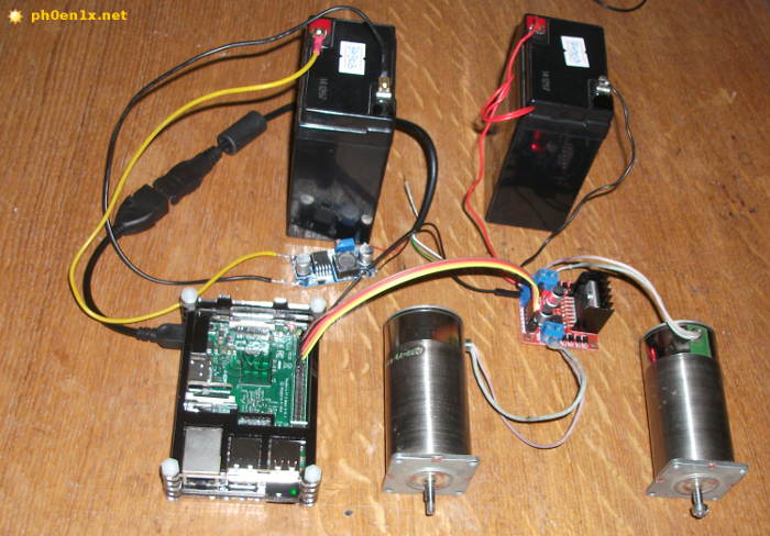
Rice. 7. L298 + Raspberry Pi + DC motors.
My mini-computer is powered through a step-down switching stabilizer from a second 6V battery. Let's move on to writing a program for our experiment; our goal is to control the rotation of the shaft of each motor using a keyboard that is connected to the Raspberry Pi or remotely via SSH, VNC.
Now let's try a simple program written in Python, which will help you understand the principle of controlling a DC motor.
We download the raspberry, open the Terminal or connect to it remotely using SSH. Create a new file and open it for editing using the command:
Nano /home/pi/l298_dc_motors_test.py
We paste the Python script code into the editor, which is given below:
#!/usr/bin/env python # -*- coding: utf-8 -*- import time import RPi.GPIO as GPIO # Prepare GPIO pins. GPIO.cleanup() GPIO.setmode(GPIO.BCM) GPIO.setup(4, GPIO.OUT) GPIO.output(4, GPIO.LOW) GPIO.setup(17, GPIO.OUT) GPIO.output(17, GPIO .LOW) # Turn on the rotation of motor 1 in one direction. GPIO.output(4, GPIO.HIGH) # wait 5 seconds. time.sleep(5) # Turn off engine 1. GPIO.output(4, GPIO.LOW) # wait 10 seconds. time.sleep(10) # Turn on the rotation of motor 1 in the other direction. GPIO.output(17, GPIO.HIGH) # wait 5 seconds. time.sleep(5) # Turn off engine 1. GPIO.output(17, GPIO.LOW)
Exit the editor and save the file. Make the script executable and run it:
Chmod +x /home/pi/l298_dc_motors_test.py /home/pi/l298_dc_motors_test.py
After starting the script, one of the engines will begin to rotate in one direction for five seconds, then it will turn off and after 10 seconds it will begin to rotate in the other direction for 5 seconds.
Below is a more complex and functional example of a program that will interact with the user and allow interactive control of two electric motors. Similar to the first script, the program can be saved to the same file or to a new one created separately.
It is important that in this code example, indentation is respected; I have already written about this before.
#!/usr/bin/env python # -*- coding: utf-8 -*- import os import sys import curses import time import RPi.GPIO as GPIO # Set the numbers of GPIO pins with which we will work M1_RIGHT = 4 M1_LEFT = 17 M2_RIGHT = 27 M2_LEFT = 22 # Function for preparing GPIO pins def setup(*ports): GPIO.cleanup() # Mode for naming pins by name, not by number on the board GPIO.setmode(GPIO.BCM) for port in ports : # Set the pin to pin + low level "0" GPIO.setup(port, GPIO.OUT) GPIO.output(port, GPIO.LOW) # Function to set low level on all pins (turn off) def stop_all(): GPIO.output(M1_LEFT, GPIO.LOW) GPIO.output(M1_RIGHT, GPIO.LOW) GPIO.output(M2_LEFT, GPIO.LOW) GPIO.output(M2_RIGHT, GPIO.LOW ) # Function for controlling the rotation of motors def rotate(motor=1, mode="s"): # Turn off all pins stop_all() # For motor 1 if motor == 1: if mode == "r": # Set high level on pin M1_RIGHT (4) GPIO.output(M1_RIGHT, GPIO.HIGH) elif mode == "l": # Set a high level on pin M1_LEFT (17) GPIO.output(M1_LEFT, GPIO.HIGH) # For motor 2 elif motor == 2: if mode == "r": GPIO.output(M2_RIGHT, GPIO.HIGH) elif mode == "l": GPIO.output(M2_LEFT, GPIO.HIGH) # Initialize the pins GPIO setup(M1_RIGHT, M1_LEFT , M2_RIGHT, M2_LEFT) # Screen initialization (curses module) stdscr = curses.initscr() # React to key presses without confirmation using ENTER curses.cbreak() # Allow the use of arrow keys on the keyboard stdscr.keypad(1) # Do not block the program by time when polling events stdscr.nodelay(1) # Display default data on the screen stdscr.addstr(0, 10, "Hit "q" to quit") stdscr.addstr(2, 10, "A - M1 Left, D - M1 Right") stdscr.addstr(3, 10, "< - M2 Left, >- M2 Right") stdscr.addstr(4, 10, "S - stop") stdscr.refresh() # Main loop while True: # Get the keystroke code and check it key = stdscr.getch() if key != - 1: # If the key is "left arrow" then rotate slider 2 to the left if key == curses.KEY_LEFT: # Display the line "M2"<---" в позиции 6, 10 stdscr.addstr(6, 10, "M2 <---") rotate(2, "l") # Если клавиша "стрелка вправо" то вращаем движок 2 вправо elif key == curses.KEY_RIGHT: stdscr.addstr(6, 10, "M2 --->") rotate(2, "r") # If the key is "a" then rotate slider 1 to the left elif key == ord("a"): stdscr.addstr(6, 10, "M1<---") rotate(1, "l") # Если клавиша "d" то вращаем движок 1 вправо elif key == ord("d"): stdscr.addstr(6, 10, "M1 --->") rotate(1, "r") # If the key is "s" then stop all engines elif key == ord("s"): stdscr.addstr(6, 10, "STOP 12") stop_all() # If the key "s" then exit the program elif key == ord("q"): # Restore previous terminal settings stdscr.keypad(0) curses.echo() curses.endwin() # Clear and exit os.system("clear" ) sys.exit() # Refresh the text on the screen and make a short delay stdscr.refresh() time.sleep(0.01)
Having launched the script, you can press the keyboard arrows “left” and “right”, as well as the keys with the letters “A” and “D” - the motors should rotate alternately and in different directions, and the program will display their current operating mode.
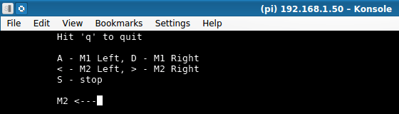
Rice. 8. Python program for controlling motors using the L298 driver (Konsole terminal, KDE).
A short video demonstration of this experiment is given below:
What is a stepper motor, types of steppers
Stepper motor(for those who don’t know) - this is an electric motor in which there are no brushes and windings on the stator (armature), they are present on the rotor and are placed in such a way that by connecting each of them to the power source, we fix the rotor (we take one step). If you alternately apply voltage to each of the windings with the required polarity, you can make the motor rotate (take successive steps) in the desired direction.
Stepper motors are reliable, resistant to wear and allow you to control rotation at a certain angle, they are used in process automation, in production, in electronic computing equipment (CD-DVD drives, printers, copiers), etc.
Such engines come in the following types:
- Bipolar- 2 windings, one for each phase, for control you can use a circuit with 2 H-bridges or one half-bridge with bipolar power supply;
- Unipolar- 2 windings, each with a tap from the middle, it is convenient to switch phases by changing the halves of each winding, simplifies the driver circuit (4 keys), and can also be used as a bipolar one without using taps from the windings;
- With four windings- universal, by connecting the windings appropriately you can use it as a bipolar or unipolar motor.

Rice. 9. Types of stepper motors: bipolar, unipolar, with four windings.
The type of motor used can, as a rule, be determined by the number of terminals on its body, and it also does not hurt to ring all the terminals with a tester to determine whether there are connections between the windings.
L298 + stepper motor + Raspberry Pi
Now let's connect the stepper motor, in my case I used a bipolar high-power stepper motor taken from an old dot matrix printer.
To connect one bipolar motor, you will need two driver outputs on L298 (two H-bridges). For this experiment, the L298 module must be connected to the Raspberry Pi in the same way as in version with.
First, you can experiment without the raspberry - apply 5V voltage to the inputs of the L298 module one by one and see how the motor shaft performs the steps.
In fact, with the help of a raspberry, we will alternately and with some delay apply impulses to the windings of the engine, thereby forcing its shaft to rotate in the direction we need and at the desired speed.
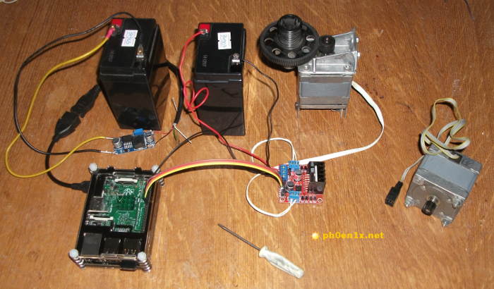
Rice. 10. Connecting a bipolar stepper motor to the L298 module for control via Raspberry Pi.
If everything is already connected, then we move on to experiments with a simple test program in Python, which will help you understand how to work with stepper motors using L298 + Raspberry Pi.
Let's create a file for the script and open it for editing:
Nano /home/pi/l298_stepper_motor_test.py
Paste the following Python script code into the editor :
#!/usr/bin/env python # -*- coding: utf-8 -*- import time import RPi.GPIO as GPIO # Prepare GPIO pins. GPIO.cleanup() GPIO.setmode(GPIO.BCM) GPIO.setup(4, GPIO.OUT) GPIO.output(4, GPIO.LOW) GPIO.setup(17, GPIO.OUT) GPIO.output(17, GPIO .LOW) GPIO.setup(27, GPIO.OUT) GPIO.output(27, GPIO.LOW) GPIO.setup(22, GPIO.OUT) GPIO.output(22, GPIO.LOW) # Time delay between steps, sec . step_timeout = 0.0105 # Pulse duration, sec. impulse_timeout = 0.008 # Step 1. GPIO.output(4, GPIO.HIGH) time.sleep(impulse_timeout) GPIO.output(4, GPIO.LOW) time.sleep(step_timeout) # Step 2. GPIO.output(17, GPIO .HIGH) time.sleep(impulse_timeout) GPIO.output(17, GPIO.LOW) time.sleep(step_timeout) # Step 3. GPIO.output(27, GPIO.HIGH) time.sleep(impulse_timeout) GPIO.output(27 , GPIO.LOW) time.sleep(step_timeout) # Step 4. GPIO.output(22, GPIO.HIGH) time.sleep(impulse_timeout) GPIO.output(22, GPIO.LOW) time.sleep(step_timeout) # Wait for 10 seconds time.sleep(10) # 20 times, 4 steps per loop. for i in range(0,20): GPIO.output(4, GPIO.HIGH) time.sleep(impulse_timeout) GPIO.output(4, GPIO.LOW) time.sleep(step_timeout) GPIO.output(17, GPIO. HIGH) time.sleep(impulse_timeout) GPIO.output(17, GPIO.LOW) time.sleep(step_timeout) GPIO.output(27, GPIO.HIGH) time.sleep(impulse_timeout) GPIO.output(27, GPIO.LOW) time.sleep(step_timeout) GPIO.output(22, GPIO.HIGH) time.sleep(impulse_timeout) GPIO.output(22, GPIO.LOW) time.sleep(step_timeout)
We make the file with the script executable and run it for execution:
Chmod +x /home/pi/l298_stepper_motor_test.py /home/pi/l298_stepper_motor_test.py
After starting the script, the stepper motor must take 4 steps (rotation in one direction), then after waiting 10 seconds it will begin its rotation again and make 20*4 steps.
Now let's look at an example of an interactive program that allows you to control the direction and speed of rotation (sequential steps) of a stepper motor using a keyboard.
#!/usr/bin/env python # -*- coding: utf-8 -*- import os import sys import curses import time import RPi.GPIO as GPIO # Function for preparing GPIO pins def setup(*ports): GPIO. cleanup() # Mode of naming pins by name, not by number on the board GPIO.setmode(GPIO.BCM) for port in ports: # Setting the pin to pin + low level "0" GPIO.setup(port, GPIO.OUT) GPIO.output(port, GPIO.LOW) # Function for sending an impulse to the pin with some delay (1 step) def impulse(port=0): GPIO.output(port, GPIO.HIGH) # Set the timeout value to be anough for one step time.sleep(0.008) GPIO.output(port, GPIO.LOW) time.sleep(timeout) # Install the pins we need GPIO setup(4, 17, 27, 22) # Delay between steps (default) timeout = 0.0105 # Rotation direction (default) direction = "r" # Screen initialization (curses module) stdscr = curses.initscr() # React to key presses without confirmation with ENTER curses.cbreak() # Allow the use of arrow keys on the keyboard stdscr.keypad(1) # Do not block the program for time when polling events stdscr.nodelay(1) # Display the default data on the screen stdscr.addstr(0, 10, "Hit "q" to quit") stdscr.addstr(2 , 10, "--->") stdscr.addstr(3, 10, "Timeout: " + str(timeout)) stdscr.refresh() # Main loop while True: # Set of pulses to rotate the motor shaft to the right if direction = = "r": impulse(4) impulse(17) impulse(27) impulse(22) # Set of impulses for rotating the motor shaft to the left elif direction == "l": impulse(22) impulse(27) impulse(17) impulse (4) # Read the keystroke code and check it key = stdscr.getch() if key != -1: # The "left" key changes the direction of rotation: LEFT if key == curses.KEY_LEFT: # display text "<---" в позиции экрана 2, 10 stdscr.addstr(2, 10, "<---") # Изменим значение переменной с направлением вращения direction = "l" # Клавиша "вправо" меняет направление вращения: ВПРАВО elif key == curses.KEY_RIGHT: stdscr.addstr(2, 10, "--->") direction = "r" # The up key speeds up the rotation elif key == curses.KEY_UP: # Reduce the delay between steps timeout = timeout - 0.0005 # The down key slows down the rotation elif key == curses.KEY_DOWN: # Increase the delay between steps timeout = timeout + 0.0005 # The "q" key exits the program elif key == ord("q"): stdscr.keypad(0) curses.echo() curses.endwin() os.system("clear" ) sys.exit() # Make sure that the delay time does not cross the border 0 if timeout<= 0: timeout = 0.0005 # Обновляем текст на экране stdscr.addstr(3, 10, "Timeout: " + str(timeout)) stdscr.refresh() time.sleep(0.01)
Now press the left and right arrow keys and see how the direction of rotation of the motor shaft will change, and when you press the up and down keys, the speed will increase and decrease accordingly.
If the motor does not rotate, then it is possible that you will need to change the polarity of connecting one of the windings to the module to L298.

Rice. 11. Bipolar stepper motor control program, L298, Raspberry Pi.
Video demonstration of the operation of a stepper motor:
Conclusion
I hope you got the answer to the question “what is an H-bridge and how does it work?” From the experiments it should be clear how to use the driver on the L298 chip and connect different engines to it.
It is important to note that on the Internet you can find ready-made libraries and scripts in Python for convenient control of motors using the H-bridge on the L298 using a Raspberry Pi.
Beginning radio amateurs are often faced with the problem of identifying radio components on diagrams and correctly reading their markings. The main difficulty lies in the large number of names of elements, which are represented by transistors, resistors, capacitors, diodes and other parts. Its practical implementation and normal operation of the finished product largely depend on how correctly the diagram is read.
Resistors
Resistors include radio components that have a strictly defined resistance to the electric current flowing through them. This function is designed to reduce the current in the circuit. For example, to make a lamp shine less brightly, power is supplied to it through a resistor. The higher the resistance of the resistor, the less the lamp will glow. For fixed resistors, the resistance remains unchanged, while variable resistors can change their resistance from zero to the maximum possible value.
Each constant resistor has two main parameters - power and resistance. The power value is indicated on the diagram not with alphabetic or numerical symbols, but with the help of special lines. The power itself is determined by the formula: P = U x I, that is, equal to the product of voltage and current. This parameter is important because a particular resistor can only withstand a certain amount of power. If this value is exceeded, the element will simply burn out, since heat is released during the passage of current through the resistance. Therefore, in the figure, each line marked on the resistor corresponds to a certain power.

There are other ways to designate resistors in diagrams:

- On the circuit diagrams, the serial number is indicated in accordance with the location (R1) and the resistance value is equal to 12K. The letter “K” is a multiple prefix and means 1000. That is, 12K corresponds to 12,000 ohms or 12 kilo-ohms. If the letter “M” is present in the marking, this indicates 12,000,000 ohms or 12 megaohms.
- In marking with letters and numbers, the letter symbols E, K and M correspond to certain multiple prefixes. So the letter E = 1, K = 1000, M = 1000000. The decoding of the symbols will look like this: 15E - 15 Ohm; K15 - 0.15 Ohm - 150 Ohm; 1K5 - 1.5 kOhm; 15K - 15 kOhm; M15 - 0.15M - 150 kOhm; 1M2 - 1.5 mOhm; 15M - 15mOhm.
- In this case, only digital designations are used. Each includes three digits. The first two of them correspond to the value, and the third - to the multiplier. Thus, the factors are: 0, 1, 2, 3 and 4. They indicate the number of zeros added to the base value. For example, 150 - 15 Ohm; 151 - 150 Ohm; 152 - 1500 Ohm; 153 - 15000 Ohm; 154 - 120000 Ohm.
Fixed resistors
The name of constant resistors is associated with their nominal resistance, which remains unchanged throughout the entire period of operation. They differ depending on the design and materials.

Wire elements consist of metal wires. In some cases, high resistivity alloys may be used. The basis for winding the wire is a ceramic frame. These resistors have high nominal accuracy, but a serious drawback is the presence of a large self-inductance. In the manufacture of film metal resistors, a metal with high resistivity is sprayed onto a ceramic base. Due to their qualities, such elements are most widely used.
The design of carbon fixed resistors can be film or volumetric. In this case, the qualities of graphite as a material with high resistivity are used. There are other resistors, for example, integral ones. They are used in specific integrated circuits where the use of other elements is not possible.
Variable resistors
Beginning radio amateurs often confuse a variable resistor with a variable capacitor, since in appearance they are very similar to each other. However, they have completely different functions, and there are also significant differences in how they are represented on the circuit diagrams.

The design of a variable resistor includes a slider that rotates along the resistive surface. Its main function is to adjust the parameters, which consists in changing the internal resistance to the desired value. The operation of the volume control in audio equipment and other similar devices is based on this principle. All adjustments are made by smoothly changing voltage and current in electronic devices.
The main parameter of a variable resistor is its resistance, which can vary within certain limits. In addition, it has an installed power that it must withstand. All types of resistors have these qualities.

On domestic circuit diagrams, elements of variable type are indicated in the form of a rectangle, on which two main and one additional terminal are marked, located vertically or passing through the icon diagonally.
In foreign diagrams, the rectangle is replaced by a curved line indicating an additional output. Next to the designation is the English letter R with the serial number of a particular element. The value of the nominal resistance is indicated next to it.
Connection of resistors
In electronics and electrical engineering, resistor connections are often used in various combinations and configurations. For greater clarity, you should consider a separate section of the circuit with serial, parallel and.

In a series connection, the end of one resistor is connected to the beginning of the next element. Thus, all resistors are connected one after another, and a total current of the same value flows through them. Between the start and end points there is only one path for current to flow. As the number of resistors connected into a common circuit increases, there is a corresponding increase in the total resistance.

A connection is considered parallel when the starting ends of all resistors are combined at one point, and the final outputs at another point. Current flow occurs through each individual resistor. As a result of parallel connection, as the number of connected resistors increases, the number of paths for current flow also increases. The total resistance in such a section decreases in proportion to the number of connected resistors. It will always be less than the resistance of any resistor connected in parallel.

Most often in radio electronics, a mixed connection is used, which is a combination of parallel and serial options.
In the diagram shown, resistors R2 and R3 are connected in parallel. The series connection includes resistor R1, a combination of R2 and R3, and resistor R4. In order to calculate the resistance of such a connection, the entire circuit is divided into several simple sections. After this, the resistance values are summed up and the overall result is obtained.
Semiconductors
A standard semiconductor diode consists of two terminals and one rectifying electrical junction. All elements of the system are combined in a common housing made of ceramic, glass, metal or plastic. One part of the crystal is called the emitter, due to the high concentration of impurities, and the other part, with a low concentration, is called the base. The marking of semiconductors on the diagrams reflects their design features and technical characteristics.

Germanium or silicon is used to make semiconductors. In the first case, it is possible to achieve a higher transmission coefficient. Elements made of germanium are characterized by increased conductivity, for which even a low voltage is sufficient.
Depending on the design, semiconductors can be point or planar, and according to technological characteristics they can be rectifier, pulse or universal.
Capacitors
A capacitor is a system that includes two or more electrodes made in the form of plates - plates. They are separated by a dielectric, which is much thinner than the capacitor plates. The entire device has mutual capacitance and has the ability to store electrical charge. In the simplest diagram, the capacitor is presented in the form of two parallel metal plates separated by some kind of dielectric material.

On the circuit diagram, next to the image of the capacitor, its nominal capacitance is indicated in microfarads (μF) or picofarads (pF). When designating electrolytic and high-voltage capacitors, after the rated capacitance the value of the maximum operating voltage, measured in volts (V) or kilovolts (kV), is indicated.
Variable capacitors
To designate capacitors with variable capacitance, two parallel segments are used, which are crossed by an inclined arrow. Movable plates connected at a certain point in the circuit are depicted as a short arc. Next to it is a designation for the minimum and maximum capacity. A block of capacitors, consisting of several sections, is combined using a dashed line intersecting the adjustment signs (arrows).

The trimmer capacitor designation includes a slanted line with a dash at the end instead of an arrow. The rotor appears as a short arc. Other elements - thermal capacitors - are designated by the letters SK. In its graphic representation, a temperature symbol is placed next to the nonlinear regulation sign.
Permanent capacitors
Graphic symbols for capacitors with constant capacitance are widely used. They are depicted as two parallel segments and conclusions from the middle of each of them. The letter C is placed next to the icon, after it - the serial number of the element and, with a small interval, a numerical designation of the nominal capacity.


When using a capacitor with in a circuit, an asterisk is placed instead of its serial number. The rated voltage value is indicated only for high voltage circuits. This applies to all capacitors except electrolytic ones. The digital voltage symbol is placed after the capacity designation.
The connection of many electrolytic capacitors requires correct polarity. In the diagrams, a “+” sign or a narrow rectangle is used to indicate a positive cover. In the absence of polarity, narrow rectangles mark both plates.
Diodes and Zener diodes
Diodes are the simplest semiconductor devices that operate on the basis of an electron-hole junction known as a pn junction. The property of one-way conductivity is clearly conveyed in graphic symbols. A standard diode is depicted as a triangle, symbolizing the anode. The apex of the triangle indicates the direction of conduction and abuts the transverse line indicating the cathode. The entire image is intersected in the center by an electrical circuit line.

The letter designation VD is used. It displays not only individual elements, but also entire groups, for example, . The type of a particular diode is indicated next to its position designation.
The basic symbol is also used to designate zener diodes, which are semiconductor diodes with special properties. The cathode has a short stroke directed towards the triangle, symbolizing the anode. This stroke is located invariably, regardless of the position of the zener diode icon on the circuit diagram.
Transistors
Most electronic components have only two terminals. However, elements such as transistors are equipped with three terminals. Their designs come in a variety of types, shapes and sizes. Their general principles of operation are the same, and minor differences are associated with the technical characteristics of a particular element.

Transistors are used primarily as electronic switches to turn various devices on and off. The main convenience of such devices is the ability to switch high voltages using a low voltage source.
At its core, each transistor is a semiconductor device with the help of which electrical oscillations are generated, amplified and converted. The most widespread are bipolar transistors with the same electrical conductivity of the emitter and collector.
In the diagrams they are designated by the letter code VT. The graphic image is a short dash with a line extending from the middle of it. This symbol indicates the base. Two inclined lines are drawn to its edges at an angle of 60 0, displaying the emitter and collector.

The electrical conductivity of the base depends on the direction of the emitter arrow. If it is directed towards the base, then the electrical conductivity of the emitter is p, and that of the base is n. When the arrow is directed in the opposite direction, the emitter and base change their electrical conductivity to the opposite value. Knowledge of electrical conductivity is necessary to correctly connect the transistor to the power source.
In order to make the designation on the diagrams of radio components of the transistor more clear, it is placed in a circle indicating the housing. In some cases, a metal housing is connected to one of the terminals of the element. Such a place on the diagram is displayed as a dot placed where the pin intersects with the housing symbol. If there is a separate terminal on the case, then the line indicating the terminal can be connected to a circle without a dot. Near the positional designation of the transistor its type is indicated, which can significantly increase the information content of the circuit.
Letter designations on radio component diagrams
|
Basic designation |
Item name |
Additional designation |
Device type |
|
Device |
Current regulator |
||
|
Relay block |
|||
|
Device |
|||
|
Converters |
Speaker |
||
|
Thermal sensor |
|||
|
Photocell |
|||
|
Microphone |
|||
|
Pickup |
|||
|
Capacitors |
Power capacitor bank |
||
|
Charging capacitor block |
|||
|
Integrated circuits, microassemblies |
IC analog |
||
|
Digital IC, logic element |
|||
|
Elements are different |
Thermal electric heater |
||
|
Lighting lamp |
|||
|
Arresters, fuses, protective devices |
Discrete instantaneous current protection element |
||
|
The same for inertial current |
|||
|
fuse |
|||
|
Arrester |
|||
|
Generators, power supplies |
Battery |
||
|
Synchronous compensator |
|||
|
Generator exciter |
|||
|
Indicating and signaling devices |
Sound alarm device |
||
|
Indicator |
|||
|
Light signaling device |
|||
|
Signal board |
|||
|
Signal lamp with green lens |
|||
|
Signal lamp with red lens |
|||
|
Signal lamp with white lens |
|||
|
Ionic and semiconductor indicators |
|||
|
Relays, contactors, starters |
Current relay |
||
|
Indicator relay |
|||
|
Electrothermal relay |
|||
|
Contactor, magnetic starter |
|||
|
Time relay |
|||
|
Voltage relay |
|||
|
Enable command relay |
|||
|
Trip command relay |
|||
|
Intermediate relay |
|||
|
Inductors, chokes |
Fluorescent lighting control |
||
|
Action time meter, clock |
|||
|
Voltmeter |
|||
|
Wattmeter |
|||
|
Power switches and disconnectors |
Automatic switch |
||
|
Resistors |
Thermistor |
||
|
Potentiometer |
|||
|
Measuring shunt |
|||
|
Varistor |
|||
|
Switching device in control, signaling and measuring circuits |
Switch or switch |
||
|
Push-button switch |
|||
|
Automatic switch |
|||
|
Autotransformers |
Current transformer |
||
|
Voltage transformers |
|||
|
Converters |
Modulator |
||
|
Demodulator |
|||
|
power unit |
|||
|
Frequency converter |
|||
|
Electrovacuum and semiconductor devices |
Diode, zener diode |
||
|
Electrovacuum device |
|||
|
Transistor |
|||
|
Thyristor |
|||
|
Contact connectors |
Current collector |
||
|
High frequency connector |
|||
|
Mechanical devices with electromagnetic drive |
Electromagnet |
||
|
Electromagnetic lock |
 How to fill out a report on the intended use of funds received
 Cheesecakes from cottage cheese in a frying pan - classic recipes for fluffy cheesecakes Cheesecakes from cottage cheese for 500 grams recipe
 The easiest zucchini casserole in the oven